Input and Output Components
The following types of components are currently supported by d.tools:
Input components sense user actions and generate events that describe those user actions to the d.tools application. Events have two functions: they can trigger transitions from one state to another in the interaction model; and they can serve as control signal sources for control connections to modify behavior of your prototype within an active state. d.tools supports two types of input components: discrete and continuous inputs.
Discrete input components have a fixed number of stages they can be in. The simplest kind of discrete input is a binary input which can only take on two values: on or off; 1 or 0. Buttons and switches are such binary discrete inputs. Discrete inputs can have more stages: 3-way switches or rotary encoders are examples. These components are not yet available in d.tools. To learn more about how discrete inputs trigger transitions, look at Pattern 1 in the page on d.tools design patterns.
Continuous input components have a range of values they can take on. In d.tools, the minimum value of a continuous controller is 0.0; the maximum value is 100.0. Sliders and knobs are examples of continuous inputs - turning a knob from its leftmost to its rightmost position will generate a long sequence of events with values starting at 0 , increasing, and ending at 100. Simple continuous controllers such as sliders and knobs operate in one range or dimension; other components can send multiple ranges of data. For example, an accelerometer transmits 3 dimensions of orientation data (X,Y and Z); a joystick transmits two dimensions (X and Y).
Continuous inputs can trigger state transitions by transforming the data values into discrete events. On a transition for a continuous input, you can specify an interval within 0.0 to 100.0. When the value received from the input component falls within the range, the transition is taken. For more information, see design pattern 4. Continuous inputs can also be used as control signal sources that send messages to control signal targets within a state. See the design pattern 7 for examples.
Hardware component |
Software representation |
 |
 |
|
|
A button can only be in one of two possible states at any point in time: either is is pressed down, or it is not pressed down. Buttons generate two types of events, whenever their state changes: when a button in up state is pressed down, a button_pressed event is generated. When a button in down state goes back up, a button_released event is generated. Buttons only stay pressed as long as the user is pushing them and then revert to their up state automatically. A key on a computer keyboard is an example of a button. A button is a binary discrete component.
Hardware component |
Software representation |
 |
|
|
|
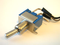
Like buttons, switches also have two possible states. Unlike buttons though, switches do not automatically toggle back to an initial state. The power switch on a surge protector is an example of this type of switch. A switch is a binary discrete component.
Hardware component |
Software representation |
 |
|
|
|
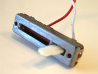
Sliders can transmit a range of values. In d.tools, input components that can transmit a range of values are called continuous controllers. In d.tools, the minimum value of a continuous controller is 0.0; the maximum value is 100.0.
Hardware component |
Software representation |
 |
 |
|
|
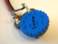
Knobs behave like sliders, but their movement is rotational, rather than linear.
Hardware component |
Software representation |
 |
 |
|
|
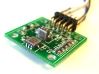
Accelerometers can sense their orientation relative to the ground along three axes: X,Y and Z. Every time the physical component is moved or rotated, the new orientation is send as a value. An accelerometer is thus a 3-dimensional continuous controller.
Output components return information back to the user of your device. You author what kind of information (images, sounds, lights) will be sent to the user in each state of the statechart diagram. Whenever a new state is made the currently active state (either by selecting it with the mouse in the d.tool software or by events generated by hardware inputs), all outputs will change to reflect the authored content. Outputs also act as control signal targes within an active state.
Hardware component |
Software representation |
 |
 |
|
|
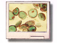
LCD screens are output components that can display images in .gif, .jpg, and .png format. Drag and drop images from the d.tools Asset Library onto a software LCD screen icon in the statechart editor to show that image whenever the chosen state is active. This guide has a separate page that describes how to add your own images to d.tools to show on an LCD screen. Currently, d.tools supports only one LCD screen per device.
Hardware component |
Software representation |
 |
 |
|
|
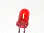
LED stands for light emitting diode. Discrete control signals can turn LEDs on and off. Through the property sheet of an LED in a statechart state you can also define fading or blinking patterns.
Hardware component |
Software representation |
 |
 |
|
|
Speakers can play back sound files in .wav format. d.tools currently uses the sound card of your computer to play back the sound files so you do not have to embed a separate speaker into your device. Drag and drop sounds from the d.tools Asset Library onto speaker symbols in a state to assign a sound file to a state. Speakers can receive both continuous and discrete control signals.