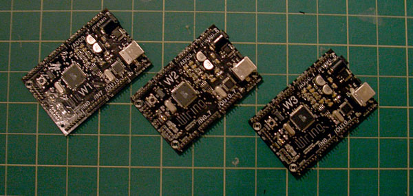
You can now use the Wiring hardware platform together with the d.tools software design environment.

(our first batch of three Wiring boards flashed with d.tools code)
What do I need to do?
First, download and install the d.tools graphical editor plug-in for Eclipse - instructions here.
Then download the following binary file for the Wiring board form this site: dtools4wiring-01.hex .
Next, program the file onto your Wiring board - we do this using the uisp.exe program that ships with WinAVR (and also the Wiring environment). Our command line looks as follows (your mileage may vary):
uisp -v -dprog=stk500 -dserial=/dev/ttyS10 -dspeed=115200 -dpart=atmega128 --upload if=dtools4wiring-01.hex
Make a note which virtual COM port your Wiring board appears as (look it up in the Device Manager in Windows) and enter that into the d.tools Preferences (Window menu->Preferences->d.tools Preferences). Restart Eclipse.
What kind of inputs/outputs are available? And how do I use them?
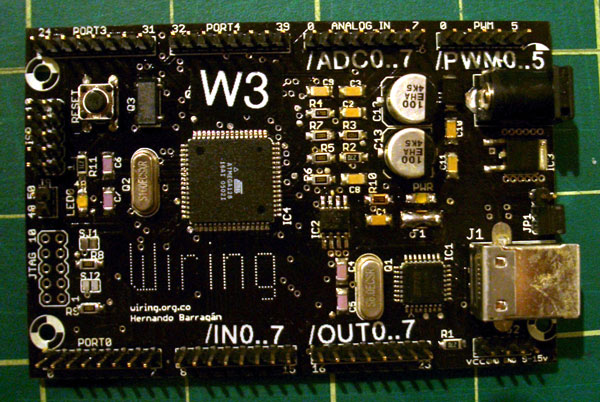
In this early version, we support 8 discrete inputs, 8 analog inputs, 8 discrete outputs and all 6 PWM channels. d.tools uses OpenSoundControl messages to address hardware - each input and output pin will have its own address (a string that looks like a file path). Here is the mapping of Wiring ports to OSC addresses:
- Wiring Board Port 1: Discrete inputs, addresses are "/in0", "/in1", ..."/in7"
- Wiring Board Port 2: Discrete outputs, addresses are "/out0" through "/out7"
- Wiring Board Analog Inputs: Addresses are "/adc0" through "/adc7"
- Wiring board PWM port: addresses are "/pwm0" through "/pwm5"
- Other ports are not currently in use.

(close-up: ports relabeled with OSC addresses)
How does this work?
The program running on your Wiring board communicates with d.tools via OpenSoundControl messages. Each time one of your inputs (discrete or analog) changes in value, the Wiring board sends an OSC message to the PC that describes the input change. The PC in return can send OSC messages back to Wiring. The messages are parsed and discrete or PWM outputs are set accordingly. In essence, you Wiring board is now a PC-controlled sensor data acquisition interface.
What about supporting Arduino?
It has its own page here.
What else can I do with my newly-flashed Wiring board?
Since data output is in OSC format, you could connect it directly to puredata (pd) to control sound synthesis. Most OSC-aware applications expect the OSC packets to arrive as UDP packets though (and not as data from a serial port), so you'll need some helper app (such as this one from Joel@CCRMA) that rebroadcasts serial OSC messages as UDP packets. Scott Wilson's dumpOSCSerial can read serial data in pd but it is only available for Linux and OSX at the moment.